
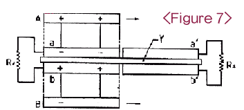
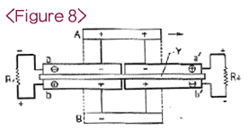
Figure 7 is the supplement to the basic principle of Patent No. 8606. It shows that the polar plate a and b in both sides of insulator(Y) are connected with resistance line R1 and the polar plate a' and b' are connected with resistance line R2. This is especially a complement to the basic principle of Patent No. 8606(Figure 3) by doing it twofold.
illustrated in Figure 3, when electricity is stored in the polar plate A and B by a D.C high voltage generator, (-) and (+) electricity are produced in a and b by electrostatic induction action. In that case, because A and B are completely insulated, it is assumed that (+) and (-) electricity of A and B once stored remain kept for a long time, and (+) and (-) electric force of A and B as marked with dotted line operate on a, a' and b, b' as long as A and B.
If, like Figure 4, A and B in Figure 3 are pushed or pulled into the direction of → , (-) electricity will be produced in a because there will appear a part escaping from (+) electric attraction of A and (+) electricity will be produced in b because there will appear a part escaping from (-) electric attraction of B, while (-) and (+) electricity flow into R1 owing to their own attractions as soon as they escape from (+) and (-) electric attraction of A and B. In that case, it is ceratin that (+) electricity of A does not have its attraction action on the outside part of dotted line in a which (-) electricity isn`t left and (-) electricity of B also does not have its attraction action on the outside part of dotted line in b which (+) electricity isn`t left. And because there appear parts taken by (+) and (-) electric attraction of A and B in a' and b', (-) and (+) electricity are produced in a' , and (+) and (-) electricity are produced in b' by making electrostatic induction occur there.
In that case, while (-) electricity of a' and (+) electricity of b' remain left as a result of being attracted by (+) and (-) electricity of A and B, (+) electricity of a' and (-) electricity of b' not affected by (+) and (-) electric attraction of A and B, (+) electricity of a' and (-) electricity of b' not influenced by (+) and (-) electric attraction of A and B flow into R2 owing to their own attractions. Accordingly, it is certain that (+) electricity of A does not have its counter-attraction action on the outside part of dotted line in a' which (+) electricity isn`t left and (-) electricity of B does not have its counter-attraction action on the outside part of dotted line in b' which (-) electricity isn`t left. Therefore, because the electric force line against the horizontal movement of A and B is toward 90˚,neither toward a and b nor toward a' and b', the following expressions are resulted.
Fx = Fcos90˚= 0
Fy = Fsin90˚= F
These expressions are the same as Patent No. 8606(Refer to pp.121~127 in Patent Official Report No. 483). But the expressions in Patent 8606 are made only when the resistance is null or weak, while the revised expressions are made even when the resistance is strong. In other words, like Figure 1, electricity flows well when the resistance is null or weak, whereas in case of Figure 3 electricity flows with its own electric attraction even when the resistance is strong.
And because the electric current flowing into R1 and R2 does not arise from magnetic field, it does not disturb the horizontal movement of A and B. Therefore, as A and B need not work for electric force and magnetic force, the electrostatic induction generator operated by this principle can generate electricity without energy being provided. But as a matter of fact, electric attraction gets weak due to the thickness of insulator(Y) and dielectric constant.
As a result, the electricity which has not become electric current comes to be left and it makes the direction of F escape from 90˚. Accordingly, the thinner the thickness gets and the lower the dielectric constant gets, the better Y is. That is, as the thickness of Y is thinner and the dielectric constant of Y is lower, the direction of F gets closer to 90˚. Now, a formula for calculating output will be described.